
Oops! I measured wrong - the radiator was to close to the water pump and the electric fan would not fit . Soooo , I lengthened the frame 4 inches to allow this to happen. I can’t believe I made this mistake after all of the frames I have built. But , it does happen. When it does, just figure out what needs to be done and fix it. But I had to also lengthen the radius rods 4 inches or move the mounting bracket for the rear of the front radius rod. I didn’t like the looks of the new position, so I welded the piece I cut out , back into the front radius rod or wishbone.

Here you can see that with the 4 inch extension, the electric fan has plenty of room to sit and give the necessary clearance needed.

With all that back tracking, it is now time to adjust the steering arms using the Ackerman principle for correct steering. I drilled a # 7 hole in the center of the differential ( rear end - measured from the backing plate flange. The hole will not be in the center of the housing because the Ford rear end is off - centered). Then I tapped the hole for a 1/4 -20 thread and screwed a short bolt into the hole with a nut to lock it in place and keep the bolt from moving around. Next I took some pink string ( used in concrete work or any color will do) and made a loop in the end and placed it over the bold and then ran it up to the front placing it right through the kingpin center on top. Extending the string out , the string should go through the steering arm hole where the tie rod end will rest. The idea here is that the steering arm needs to be heated and bent out to make this happen.
When the steering arms are in back of the axle, the arm can usually be heated and bent to where it will be in perfect alignment. When it is in front of the axle, the arms can only be bent outward until the tie rod end just clears the backing plate or rotor. It won’t always be perfect, but as close as you can get it will work just fine.
If the Ackerman principle is not used , when you turn the car to the left or right, the outside tire on the turn will turn sharp and the inside tire will turn wide thus making it harder to steer , create tire wear , and sometimes the tires will even hop. Not cool! This little adjustment needs to be done if the wheel base is longer or shorter than the original that the axle and steering arms were made for.
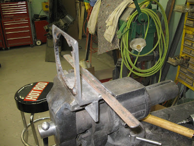
 In order to hold, heat and bend the steering arms, I built a fixture shown in the picture. I used some 3 x 5 x 1/4 inch angle iron about 5 -6 inches long with a 2 x 1/4 x 4-5 inch piece of flat bar welded to the 3 inch side so that I could clamp it in the vise. Next I cut out the center to match the larger step in the spindle and drilled the 4 1/2 inch holes for mounting. The 1 x 1/8 inch strap that is tacked to the 3 inch lip is use as a reference when measuring how far the arm is bent. This takes care of the in and out measurement. The up and down is handled from the table to the bottom of
the spindle.

This just shows a back view of the fixture mounted in the vise.

This view shows the spindle mounted in the fixture that is mounted in the vise.

With everything mounted, I needed to have some way of moving the arm when it is heated. In the past I have used large crescent wrenches or pipe wrenches, but these are crude at best. I decided to use a 1 x1 inch by about 2 foot long piece of solid bar stock for the leverage that is needed. To attach the bar to the steering arm, I drilled and tapped a 1/2 - 13 inch tread so I could use a 1/2 inch coarse bolt. The tab on the front of the bar is used to keep the bar from moving once the bend is in progress. This is just a 1 - 1 1/2 x 1/4 inch piece of flat bar welded to the top of the solid bar. The side that this is placed on , determines the force I can use to bend the arm in or out. The opposite end of the bar has a 1/2 inch hole drilled in it and is used to bolt to the arm to move it up or down when only that direction is needed for clearance. I only bend in one direction at a time , measure , heat and then bend in the other direction. Always let the arm cool naturally and never quench it in water - this could cause cracks in the metal and failure when in use. You will know when the arm is hot enough to bend when you can move it fairly easy with just your arm and a little body weight. Don’t use a hammer to help it along, this could tear the metal being heated and cause stress cracks and part failure.

Here is the arm bent with a tie rod end it place with just enough clearance between the backing plate and the rod end.

Here both arms have been bent and the entire tie rod installed and the ackerman checked with the pretty pink string. Close is good because the arms are in the front of the axle.


